# 10.9.2 Fence Boundary
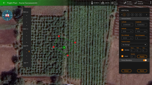
Before drawing the fence, ensure that the user enables the fence by using the enable/disable button available in front of the fence boundary. After enabling it, the user can draw the fence around the vertical plan.
As the user draws the fence around the vertical plan by clicking at the location on the map, it will be added in green color around the vertical object, as shown in the following screen.
Vertical Plan Fence
To delete a fence, the user can select a fence point and click on the "Clear" button. This will remove the selected fence point, allowing for easy modification of the fence boundary.
{% hint style="info" %}
Note: To draw a fence around the Vertical plan, the user must add at least 3 fence points.
{% endhint %}
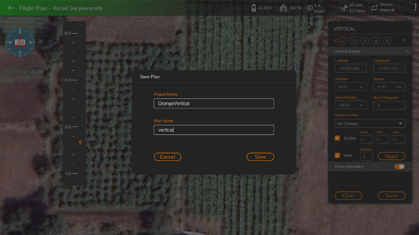
After completing the vertical details and fence boundary, the user must save the plan by clicking on the "Save" button. This will prompt the following screen, allowing the user to enter a project name and plan name for saving the plan.
Save Vertical Plan
Click on the "Save" button after entering the project name and plan name. This will save the vertical survey plan in the project and ask the user, "Plan is saved, do you want to upload plan in the device?" as shown in the following screen.
Vertical Plan Save
Click on "**Yes**" if the user wants to upload the plan to the device. It will upload the plan to the device and will ask the user, "Flight plan uploaded, proceeding for flight" as shown in the following screen.
{% hint style="info" %}
Note: At this stage, if the drone/vehicle is not connected to AeroGCS ORANGE, the system will prompt you to establish a connection. Follow the on-screen instructions to connect with the device/drone. For more details, please refer to the "Connecting a Drone" section in this manual.
After connecting the drone, navigate to the project menu by clicking on the and selecting the desired project and plan. The saved plan view will be displayed. Click on the "Upload" button to transfer the plan to the device/drone and proceed with the mission.
{% endhint %}
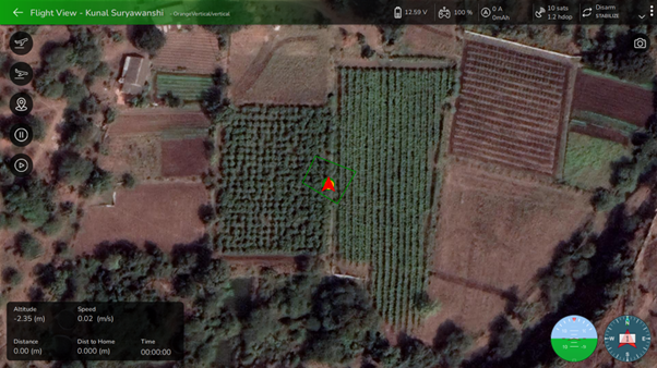
Proceed Vertical Flight
After clicking the "**OK**" button, it will proceed with the flight, and the following fly view will be displayed on your screen.
Vertical Plan Fly View
Now, the user is ready to fly the vehicle/drone by pressing the "Fly" button.

 and selecting the desired project and plan. The saved plan view will be displayed. Click on the "Upload" button to transfer the plan to the device/drone and proceed with the mission.
{% endhint %}
and selecting the desired project and plan. The saved plan view will be displayed. Click on the "Upload" button to transfer the plan to the device/drone and proceed with the mission.
{% endhint %}